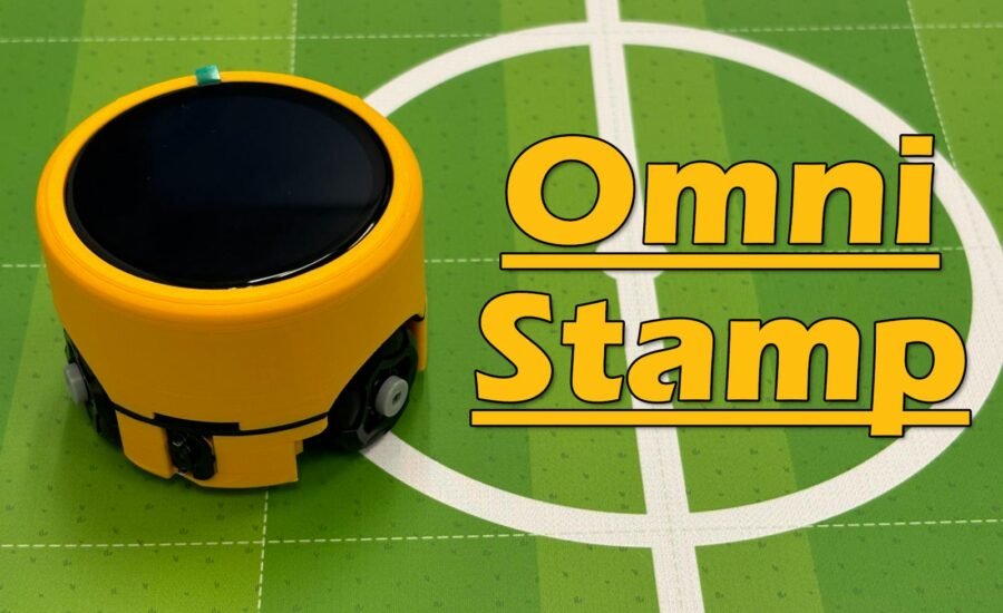
OmniStamp is a miniature three-wheel omnidirectional robot built around the M5Stack StampS3A. It uses omni wheels just 24 mm in diameter and an OID positioning module that gives the robot its absolute coordinates and heading on the field. The low-level hardware is driven by MicroBlocks firmware, while its high-level behavior can be built and modified in real time with graphical blocks.
It Started with a 24 mm Omni Wheel
This project did not begin with a complicated requirements document. It began when I came across a 24 mm omni wheel on Taobao.
Most omnidirectional robots are fairly large because their wheels, gear motors, battery, and controller take up a considerable amount of space. That tiny wheel immediately gave me an idea: could I build a truly miniature and adorable three-wheel omni robot—one small enough to fit in the palm of my hand?
With three omni wheels arranged 120° apart, the robot can move forward, backward, sideways, diagonally, or rotate in place without first turning toward its destination. This freedom of movement is fascinating, but it also creates a challenge. Open-loop control of three DC gear motors cannot move a robot accurately to a specified position. Wheel slip, motor-to-motor variation, and changes in battery voltage all introduce errors that accumulate over time.
I therefore decided to add an OID positioning module. On a map printed with positioning information, the robot can read its absolute X and Y coordinates as well as its heading. This upgrades the control objective from “move in this direction for a certain amount of time” to “move to this target point on the map.” OmniStamp is no longer simply a tiny remote-controlled vehicle; it is a desktop robot that knows where it is.
Squeezing Every Millimeter in Fusion 360
I began by modeling the omni wheels, gear motors, and mounting points in Fusion 360, then designed the chassis around a three-wheel layout with 120° spacing. To keep the robot as compact as possible, I chose right-angle N20 gear motors rather than conventional straight-shaft versions. The selected motors are rated for 6 V and have a no-load speed of 190 rpm.
Three-wheel chassis and drivetrain
The hardest part of designing something this small is making every component coexist within the limited space. The three motors must not interfere with one another, and the underside must provide the OID sensor with an unobstructed field of view and the correct operating distance. At the same time, the PCB, battery, display, USB connector, and enclosure all need their own space.
Designing the Robot Mainboard Around the StampS3A
I selected the M5Stack StampS3A kit as the main controller. It is compact, powerful enough for the project, and exposes plenty of GPIO through two rows of 1.27 mm connectors. This makes it easy to install and replace during development. The tradeoff is that it requires a relatively sophisticated external charging and power-management circuit.
I designed a robot baseboard shaped around the three-wheel structure. It integrates the following functions:
- A 2S lithium battery charging circuit based on the IP2326;
- A DC-DC power supply based on the TPS563202DRLR for the controller, sensors, and peripherals;
- Three brushed DC gear-motor drivers based on the MS8837;
- An interface for the OID positioning sensor;
- Two physical buttons, A and B. Button B is also connected to an MPS003 press-and-hold power-control IC that manages the DC-DC converter;
- A power-management circuit that disconnects the battery supply and charges the battery while USB is connected, then switches the mainboard back to battery power after USB is removed.
Two surface-mount female headers raise the StampS3A above the mainboard. This creates enough clearance to route the FPC cable while also allowing more components to fit underneath the controller. The OID positioning sensor sits at the exact center of the PCB, allowing it to report the robot’s position directly without requiring an additional coordinate transformation.
OmniStamp mainboard design
The PCB is shaped as three outward-extending sections arranged around the wheel modules. This makes use of space that would otherwise be wasted between the wheels, while placing the buttons, connectors, and motor drivers close to their corresponding mechanical parts.
Redesigning the Enclosure for a Better Display
The first version used the small rectangular display included with the StampS3A kit. It could display text and status information perfectly well and was convenient for software validation, but it never looked quite right on top of a circular robot.
The first enclosure with the original small display
I later found a 1.8-inch circular display with a resolution of 360 × 360 pixels. It covers almost the entire top of the robot. Combined with the cylindrical enclosure, its black glass surface looks more like the robot’s “face” and gives the prototype a much more finished appearance. I developed the SPI driver for the circular display and tested it in the MicroBlocks IDE.
Testing the circular display with MicroBlocks
Changing the display introduced a new set of challenges. Its dimensions, mounting method, cable direction, and interface were all different, so I redesigned the top cover and created a custom FPC adapter. This converts the circular display’s 18-pin FPC contacts into an FPC tail compatible with the 8-pin connector on the back of the StampS3A.
Comparison between the small-display and circular-display versions
Custom FPC adapter for the circular display
The enclosure retains its cylindrical profile, with an opening at the center of the underside for the OID sensor. The upper and lower shells form clearly separated layers, making the robot easier to assemble and maintain.
Keeping Robot Behavior in the MicroBlocks Layer
Once the hardware was complete, I developed MicroBlocks firmware and a set of robot blocks for OmniStamp.
MicroBlocks offers an important advantage for a project like this: the low-level firmware only needs to be implemented once. The motors, display, buttons, and positioning sensor can then be exposed as intuitive graphical blocks. From that point on, changing the motion logic, creating an interactive effect, or developing a robotics lesson no longer requires recompiling and flashing an entire Arduino project.
High-level programs can be assembled graphically, connected over BLE, and modified and tested quickly while the robot is running. MicroBlocks also supports multiple scripts running concurrently, so position updates, display animations, button interaction, and motion control can be organized independently instead of being forced into one enormous main loop. In an educational setting, learners work with concepts such as “move to target point, ” “read X position, ” and “draw an image on the display, ” rather than motor pins, SPI initialization, and communication packets.
This is the main reason I chose MicroBlocks: the complexity still exists, but it lives at the right level. The firmware drives the hardware reliably, while block-based programs express the ideas.
The Finished Robot
The final OmniStamp preserves the compact proportions of its three-wheel omni chassis, while the circular display has become its most distinctive visual feature. On an OID map, the robot can determine its absolute position, providing a foundation for point-to-point movement, trajectory drawing, multi-robot collaboration, and tabletop robot soccer.
MicroBlocks also makes it easy to create a virtual joystick or directional buttons and immediately observe the robot’s omnidirectional movement.
For more tactile control, OmniStamp can also be driven with a physical gamepad.
Controlling OmniStamp with a physical gamepad
A phone-based controller is even more portable and is ideal for quickly connecting to the robot for activities such as robot soccer.
Using a phone to control OmniStamp in a robot soccer game
What’s Next
In the future, I plan to explore trajectory drawing, multi-robot collaboration, and more expressive faces and status displays on the circular screen.
What began with a single 24 mm wheel eventually became a complete robot combining mechanical design, PCB design, power management, motor control, absolute positioning, a graphical display, and block-based programming. OmniStamp may be small, but it is already capable of supporting a wide range of interesting robotics experiments.