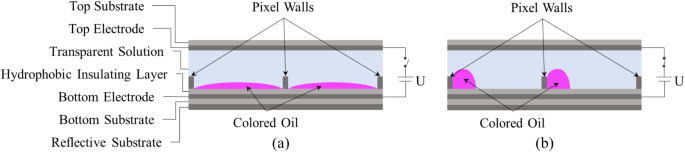
As with microlenses30, digital microfluidics (DMF)31 and other EWOD devices, EWDs are devices which utilize the electrowetting force to manipulate liquid droplets into deformation or displacement. A pixel is the smallest display unit of EWDs, which can be conceptualized as a voltage-based optical switch. The typical structure of an EWD pixel is a sandwich-like structure, as illustrated in Fig. 1. Top and bottom substrates provide both protection and support, with a reflective layer on the outside of the bottom substrate for light reflection. Each of the two layers of the substrate has an inner layer of electrodes for applying an electric field. The inner side of the bottom electrode is wrapped by a HIL which serves to inhibit electrolysis of the electrode and reduce the contact angle. The colored oil is situated on the surface of the HIL and contained by the surrounding pixel wall.

A simplified diagram of the pixel structure of EWDs and the state of colored oil at different driving voltages. (a) In the absence of an applied electric field, the colored oil located on the HIL naturally spreads and covers the entire pixel area. (b) As the driving voltage is raised, the colored oil film will gradually shrink into a droplet under the squeezing action of the solution. The remaining space in the pixel was occupied by the transparent solution.
The hydrophobicity of the bottom HIL is responsive to an applied electric field, which initiates a transformation in the droplet contact angle. In EWDs, the contact angle of the solution on the surface of the HIL with the driving voltage can be described according to the Young-Lippmann equation32.
$$\:cos\theta\:\left(U\right)=cos{\theta\:}_{0}+\frac{{\epsilon\:}_{0}{\epsilon\:}_{r}}{{2d\gamma\:}_{OW}}{U}^{2}$$
(1)
Where, \(\:U\) represents the magnitude of the driving voltage. \(\:\theta\:\) is the contact angle of solution on the surface of the HIL at the current driving voltage, and \(\:{\theta\:}_{0}\) is the initial contact angle. \(\:d\) represents the thickness of the HIL. \(\:{\gamma\:}_{OW}\) is defined as the surface tension coefficient at the oil-water interface. \(\:{\epsilon\:}_{0}\) is the dielectric constant in vacuum and \(\:{\epsilon\:}_{r}\) is the relative dielectric constant of the HIL. When the contact angle is changed under the applied voltage, the colored oil can be squeezed by the solution. Under the action of the solution, the colored oil can be forced to shrink or spread, thus switching the pixel between “on” state and “off” state.
H. J. J. Verheijen and Menno W. J. Prins conducted a study of charge trapping based on the principle of virtual displacement and found a contact angle modulation relation16 in the presence of a trapped charge, as shown in Eq. (2).
$$\:cos\theta\:\left(U\right)=cos{\theta\:}_{0}+\frac{{\epsilon\:}_{0}{\epsilon\:}_{r}}{{2d\gamma\:}_{OW}}({U-{U}_{T})}^{2}$$
(2)
Where, \(\:{U}_{T}\) is the potential of trapped charges. When a voltage is applied, the colored oil in a pixel undergoes a deformation and displacement process. The top view of the pixel at different driving voltages is depicted in Fig. 2. When the driving voltage is 0 V, the colored oil is allowed to spread naturally within a pixel, thereby demonstrating the inherent color of the oil film. At this time, the pixel is in “off” state, as illustrated in Fig. 2a. When the driving voltage is higher than a specific voltage, the colored oil contracts under the influence of the electric field, thereby revealing the color (white) of the substrate. At this time, the EWD pixel is in “on” state, as shown in Fig. 2b.

The distribution of colored oil in a pixel at different driving voltages. (a) The “off” state of a pixel when no voltage is applied. (b) The “on” state of a pixel when a specific voltage is applied.
To obtain the distribution of colored oil in a pixel, the ratio of the area of non-oil covered to the area of the pixel is defined as the aperture ratio of the pixel, as illustrated in Eq. (3).
$$\:{R}_{A}=\frac{{A}_{pixel}-{A}_{oil}}{{A}_{pixel}}\times\:100\text{\%}$$
(3)
Where, \(\:{A}_{pixel}\) and \(\:{A}_{oil}\) denote the area of the pixel and the area covered by colored oil on the HIL within the pixel, respectively. If the side length of a square pixel is \(\:a\), the area covered by the colored oil can be expressed as Eq. (4).
$$\:{A}_{oil}=\left(1-{R}_{A}\right){a}^{2}$$
(4)
An equivalent schematic of the side of a pixel is depicted in Fig. 3. During the driving process, the morphology of colored oil can be conceptualized as a spherical crown33. From the longitudinal section of the pixel, the curved oil-water interface can be approximated as a portion of the central cross-section circle of the spherical crown. The dashed portion of the diagram illustrates the initial state of colored oil in the absence of an applied voltage.

A schematic representation of the geometric relationships in the EWD pixel. The dashed line represents the oil-water interface in the absence of an applied voltage. The solid line illustrates the oil-water interface when a specific voltage is applied.
It is assumed that the colored oil remains in the shape of a spherical crown with a constant volume during the deformation and displacement processes. From the geometric relationship depicted in Fig. 3, the area covered by the colored oil on the HIL within the pixel can be expressed with the contact angle of the colored oil, as illustrated in Eq. (5).
$$\:{A}_{oil}=\pi\:{r}^{2}=\pi\:{\left(sin{\theta\:}^{{\prime\:}}\sqrt[3]{\frac{3\,V}{\pi\:(2-3cos{\theta\:}^{{\prime\:}}+{cos}^{3}{\theta\:}^{{\prime\:}})}}\right)}^{2}$$
(5)
The radius of the circle representing the bottom cross-section of colored oil is denoted by \(\:r\), the volume of colored oil is represented by \(\:V\), and the contact angle of colored oil on the HIL is designated by \(\:{\theta\:}^{{\prime\:}}\).
Following the methodology elucidated in the aforementioned reference [17], two intervening variables are introduced to resolve the contact angle of colored oil.
$$\:\alpha\:=\frac{{A}_{oil}}{{\left[\pi\:{\left(\frac{3\,V}{2}\right)}^{2}\right]}^{\frac{1}{3}}}$$
(6)
$$\:\beta\:=\sqrt[3]{16+8{\alpha\:}^{3}+{\alpha\:}^{6}+2{(4+{\alpha\:}^{3})}^{\frac{3}{2}}}$$
(7)
Subsequently, the cosine of the oil contact angle can be expressed with the two intermediate variables \(\:\alpha\:\) and \(\:\beta\:\), as illustrated in Eq. (8).
$$\:cos{\theta\:}^{{\prime\:}}=\frac{{\alpha\:}^{2}}{\beta\:}+\frac{\alpha\:\beta\:}{4+{\alpha\:}^{3}}-1$$
(8)
In the EWD pixel, the contact angle of colored oil and the contact angle of solution are complementary to each other. Consequently, there exists a relationship between the two contact angles, as described in Eq. (9).
$$\:cos\theta\:={cos}\left(\pi\:-{\theta\:}^{{\prime\:}}\right)=-cos{\theta\:}^{{\prime\:}}$$
(9)
By combining Eq. (2) and Eq. (9), \(\:{U}_{T}\) can be expressed as Eq. (10).
$$\:{U}_{T}=U-\sqrt{-\frac{{2d\gamma\:}_{OW}}{{\epsilon\:}_{0}{\epsilon\:}_{r}}(cos{\theta\:}^{{\prime\:}}+cos{\theta\:}_{0})}$$
(10)
By associating Eq. (4), Eq. (7), Eq. (8), and Eq. (10), \(\:{U}_{T}\) at any given moment can be determined from \(\:{R}_{A}\).
Subsequently, the charge density \(\:{{\upsigma\:}}_{\text{W}}\), which is formed in the aqueous phase, can be determined by employing Eq. (11).
$$\:{\sigma\:}_{W}=\frac{{\epsilon\:}_{0}{\epsilon\:}_{r}(U-{U}_{T})}{d}$$
(11)
Following the established definition of the electrowetting force, the electrowetting force \(\:{{\upgamma\:}}_{\text{E}W}\) can be expressed as Eq. (12).
$$\:{\gamma\:}_{EW}=\frac{d}{2{\epsilon\:}_{0}{\epsilon\:}_{r}}{\sigma\:}_{W}^{2}$$
(12)
An experimental platform has been constructed to measure the dynamic aperture ratio of EWD pixels. The platform consisted of a driving system and a detection system, as shown in Fig. 4. The driving system was comprised of a high-precision programmable power supply and a corresponding control software. The primary function of this system was to provide precise driving voltage for EWD pixels. The detection system was an optical detection system which employed a combination of an optical microscope, a charge-coupled device (CCD) digital camera, and optical analysis software. The optical microscope and the CCD camera were employed to capture video images of EWD pixels. Subsequently, the optical analysis software was tasked with the analysis of the video recorded by the CCD camera in real time.

The experimental platform for the measurement of pixels’ aperture ratio. (a) The control software of programmable power supply. (b) The CCD digital camera. (c) The Magenta EWD panel. (d) The programmable power supply. (e)The optical microscope. (f) The optical analysis software.
The experimental samples used in this study were magenta EWD panels independently prepared by South China Normal University. In the used EWD panel, the static contact angles of colored oil and transparent liquid on the HIL are 10° and 124°, respectively. The colored oil is a mixed solution of n-decane and anthraquinone, with a mass fraction of 10%. The transparent liquid is deionized water, which is non-polar in nature. Relevant parameters of a pixel are presented in Table 1. The experimental sample, which was connected to a power source, was positioned on the stage of an optical microscope. After establishing the optimal focal length, the appropriate pixel was selected as the observation object. Then, an appropriate driving voltage should be configured in the power supply control software. Finally, the CCD camera was activated to start recording the video magnified by the optical microscope before the power supply was turned on. The real-time aperture ratio of the pixel was acquired by the optical analysis software through a frame-by-frame analysis of the recorded video. All experiments were conducted in accordance with standard temperature and pressure conditions.